
How to Choose an Inline Thickness Measurement System Posted in: Thickness Measurement, Updates – Tags: AR700, Touch Panel Display
The key factors in choosing an inline thickness measurement system are the target material and the type of measurement you need. Your material decides the sensor technology, so start there, then focus on your accuracy, range and speed needs. Opaque materials suit a laser thickness gauge; clear ones need a confocal sensor. If the material rests on a reference surface like a conveyor or table, one laser sensor can measure thickness. Otherwise, two opposed lasers measure the material more accurately as it passes between them.
What type of material are you measuring?
Opaque materials (metal, rubber, wood, boards): laser triangulation sensors fit. They need to see a diffuse reflection of the laser spot, and a consistent white, matte surface is the ideal target. For an example, see our rubber conveyor belt thickness guide.
Dark materials such as black rubber can be measured, though exposure time may need adjusting, and more powerful laser diodes are available.
Shiny targets often reflect enough light to measure. For very shiny surfaces, tilting the laser slightly relative to the target can help.
Hot, glowing materials are hard for red lasers, so other wavelengths such as blue are offered.
Transparent materials (clear film, polymers): laser triangulation is not recommended; white-light confocal sensors are better suited. Confocal sensors can typically measure transparent, opaque, polished or rough samples in metal, glass, ceramic, semiconductor or plastic.
One sensor or two: which is best for non-contact thickness measurement?
If the material rests on a reference surface like a conveyor or table, one sensor can measure thickness; otherwise, two opposed lasers measure the material passing between them for inline measurement.
With one laser, surface imperfections, warping and vibration can degrade results, so single-laser setups are mostly used in R&D or tightly controlled environments, and dual opposed lasers are the most common approach.
For clear film, one confocal probe can work alone: it reads both the front and back faces from one side, and the difference between the two points is the thickness.
How accurate does a thickness measurement system need to be?
Within a sensor family, shorter measurement ranges are typically more accurate, since there are more detector pixels per unit distance. Using only a small slice of the range of a device keeps error closer to the resolution. Using the full range pushes error closer to the linearity.
To understand resolution vs. accuracy, picture a ruler.
Resolution is how fine the tick marks are: it’s the smallest change the sensor can notice.
Accuracy is whether the ruler is telling the truth: how close the reading is to the real thickness.
Your real-world accuracy, on a cooperative target, lands somewhere between the two. See our article on Accuracy, Linearity and Resolution Explained.
When it comes to typical tolerances, it varies by material. Transparent films and lab setups reach micron or sub-micron accuracy, while larger, rougher products moving on a conveyor, like wood, typically work in thousandths of an inch.
Example tolerances from Acuity applications:
| Material | Result reported by Acuity | Setup |
|---|---|---|
| Clear film on a moving web | ±0.6 µm (goal was better than 1 µm) | Confocal probe, one side, 1,000 samples/sec |
| 10 mm gauge block (lab demo) | Sub-micron: displayed 9.9993–9.9997 mm | Two AR700 laser sensors, zeroed on the block |
| Wooden doors on a conveyor | Within a few thousandths of an inch | Dual opposed laser sensors |
| General non-contact thickness | 0.1 mm and better | Laser displacement sensors |
How does line speed affect thickness readings?
Speed affects an inline thickness measurement system in three ways:
- Spacing between data points
- Vibration and flutter, which grow with speed
- Light on the target
1. Spacing between data points. A sensor takes discrete samples, so the faster the line moves, the more material passes between readings. A simple formula:
distance between readings = line speed ÷ sample rate
Our clear film case study shows the math: at 25 ft/min and 1,000 samples per second, the customer got a data point every 0.005″ along the film. Spacing like that keeps thin spots or defects from slipping between readings.
2. Vibration and flutter, which grow with speed. This is the bigger risk for two-sensor systems. Our copper thickness case study shows that if the two sensors aren’t synchronized, they can fire at slightly different moments and catch the material at different positions, making the thickness look falsely thicker or thinner.
That customer’s line runs at up to 700 ft/min, and even though you can’t see it, the material moves up and down slightly. Synchronized sampling cancels that motion out, so it’s the first thing to require on a fast line.
Synchronization has a speed cost. The AR700 Laser Displacement Sensor samples at up to 9,400 Hz, but its trigger mode for syncing multiple sensors cuts the maximum to 4,500 Hz. That’s still fast. At 700 ft/min (about 140 in/s), 4,500 synced samples per second works out to a reading roughly every 0.03″.
3. Light on the target. A triangulation sensor’s detector collects light over its exposure time, and longer exposures pick up weak reflections better. Faster sampling means shorter exposures, which is harder on dark or shiny materials. That’s why here at Acuity, we offer higher-power laser diode upgrades on the AR700 to keep sample rates high on dark surfaces or in bright ambient light.
How do you mount and align sensors for inline thickness measurement?
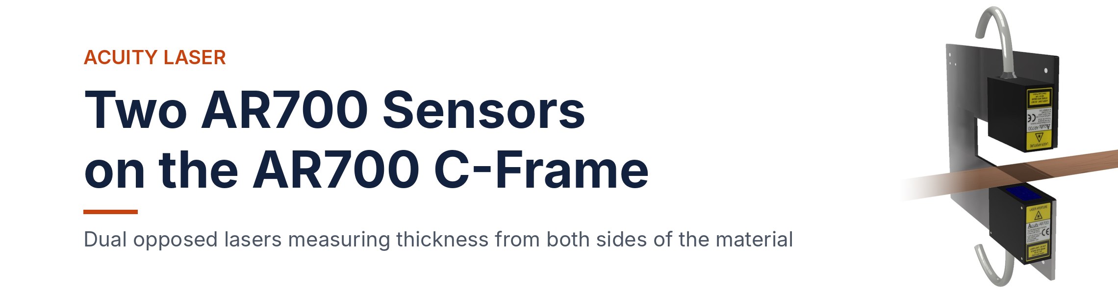
For two opposed sensors, Acuity sells a ready-made mount: the AR700 C-Frame. This mount holds two AR700 sensors facing each other for a thickness measurement system. It fits AR700 models with ranges from 1/8″ to 4″, and has M3 and M6 threaded holes for attaching the sensors and bolting the frame to your machine.
The AR700 C-Frame suits thin, precise products like strip, sheet and film. For wider gaps, see our guide on Best Practices for Building Mounts for Laser Measurement Sensors.
For laser sensor thickness alignment, the two laser spots must hit the exact same point from opposite sides, across the whole measuring range. Otherwise the system isn’t measuring true thickness.
Our simple test: hold a thin sheet of paper between the sensors so you can see both spots through it, then move it through the full range and confirm the spots stay on top of each other. On a production line, misalignment can be the difference between good product and scrap.
For reading the data, the 8-inch Touch Panel Display controls up to six Acuity sensors over serial connections and has built-in software that calculates thickness and other dimensions without a computer or programming. Plug in two sensors, set the mode to thickness, and it works as a thickness gauge. Six sensors means up to three thickness points across the material.
To see a two-sensor setup in action, watch Simple Thickness Measurement Setup with the Touch Panel Display and Two AR700s.
For automated control, the sensors can feed a PC or PLC directly. In our steel strip thickness case study, the PLC or computer receives both sensor readings and calculates thickness from the known distance between the sensors.
Prefer a complete system instead of building one? Acuity’s Thickness Measurement Solution is a turnkey package: non-contact laser sensors plus an industrial computer that measures material thickness continuously, in real time.
What details should you have ready before choosing a system?
Have these details ready:
- Material: what it is and what it looks like
- What the material is (steel, rubber, film, wood, foam)
- Color: dark materials may need exposure changes or a more powerful laser
- Finish: matte, glossy or mirror-like
- Whether it’s transparent
- Whether it’s hot or glowing
- Thickness range:
Give the thinnest and thickest product you run, plus how much the material moves up and down or shifts position. We recommend our sensor range using the difference between minimum and maximum dimensions plus where the material can sit between the sensors. Since a shorter range means better accuracy, this number has a big effect on what’s possible. - Tolerance:
Let us know the accuracy you need on your final thickness, not on each sensor. With two opposed sensors, the two sensors’ errors add together, so the system has to meet your tolerance as a whole. - Line speed:
Give your top speed and how often you need a reading along the material. Fast-moving material needs fast, synchronized sampling to capture an instant snapshot instead of an average. - Width and number of measurement points:
Let us know the material width and how many points across it you want to measure. - Support and setup:
Does the material rest on a conveyor, table or roller, or pass through freely? This decides one sensor vs. two. - Vibration or Tilt:
Does it vibrate, flutter or tilt? - Environment:
Let us know about temperature, dust, smoke, steam and ambient light. Temperature affects both the electronics and the fixture, and dirt in the beam path can block readings.
Frequently asked questions
Can a laser thickness gauge measure a textured or non-flat surface?
Yes. A point sensor can average many readings as the material passes, smoothing out a textured surface. A 2D laser profiler captures a full line across the width for averaging.
Can non-contact thickness measurement replace manual gauges and micrometers?
In most inline applications, yes. Laser sensors measure continuously as the material passes, without touching or marking the surface.
Can a laser measure hot material on the line?
Often, yes. Glowing material is hard for red lasers, so other wavelengths are used, and the sensor needs protection from the heat. Brian Harper at Acuity can confirm the right setup.
Can thickness readings be logged to a PC?
Yes. Sensors can send readings straight to a PC or PLC. The 8-inch Touch Panel Display also calculates thickness on its own and can export readings to a USB drive.
Not sure which setup fits your line? Talk to Brian Harper at Acuity about your material and line speed.