What to Do When Your Sensor is Askew
Or Measuring Around Obstacles: Setting Up Your Laser Sensor Intentionally Askew
When mounting your Acuity sensor, it’s important to align the laser as perfectly parallel as possible to the dimension you’re measuring. For the rest of this article, we will call the imaginary line that is perfectly in the direction you want to measure the “dimensional axis.” Any deviation the laser has from the dimensional axis will cause what we call a “cosine error.”
But what if you simply can’t, or can’t tell if you have? Don’t worry! Much like the least popular Huey Lewis and the News song, “The Power of Math” is here to save you!
Since it’s called a “cosine error” you’re probably expecting some trigonometry. While you can use trigonometry, there is a simpler and more accurate way to correct your measurements by simply using objects of known size.
The Easy Way: Using Standards
When an Acuity sensor is off of the dimensional axis, the error caused will be proportional to the actual distance. You can use this to your advantage by measuring one or more objects of known size–what we’d call “standards.” A standard can be any object of known size, but beware! Any error in the measurement of that object will carry into your correction. The best standards are objects that are not just precisely measured, but precisely flat and rectangular so the opposite sides are perfectly parallel to each other. So what standard should you use?
Gauge blocks are the most commonly used standards in smaller measurements. They are milled to precise, traceable dimensions. There is, however, a catch. Gauge blocks are usually made of either metal polished to a mirror finish or ceramic that is somewhat translucent. Both present challenges for laser measurement sensors.
For metal gauge blocks, the mirror finish makes it a challenge to get enough diffuse reflection back to allow a triangulation sensor like the AR700 to make an accurate measurement. The most common way to cope with this is to use a matting spray onto the reflective surface. There are sprays specifically designed for this purpose (a good search term is “3D scanning spray”) but you can also use a powdered athlete’s foot spray. The difference is that specialty sprays will be manufactured to known tolerances, so they are best for very precise applications.
For ceramic gauge blocks, the laser light bleeds into the ceramic a bit. These give better diffuse reflections without modification, but the reflection isn’t a tight point because the light bleeds in all directions. There isn’t a simple spray to help with this effect, unfortunately. Ceramic gauge blocks can be used, but it is more difficult to quantify the errors the material will cause.
Other objects can be used as standards, and you can even make your own, but the opposing sides need to be as flat and as parallel to each other as possible. Any deviation, roughness, or angle difference will cause error. You can likely get away with this when measuring the length of logs, but more precise measurements require more precise standards.
So Now You Have a Standard. How Do You Use It?
This is the simple part. You need two measurement points. This could be using two different standards, or it could be measuring the standard and a surface the standard sits against. Just be aware that all the error caveats apply to any surface you measure to.
It is very important that the standard or standards are oriented correctly. The opposing sides of the standard should be as perfectly perpendicular to the dimensional axis as possible. This is easiest if the standards can be placed on a flat surface that is already in the correct orientation. Any deviation within the standards introduces its own cosine error. Fortunately, cosine errors are very small when the angle error is small.
Once you have the orientation down, take the two measurements. Then, take the difference between them and the known distance between the two standards (or between the standard and the surface), and put them into the following equation to get a correction factor:

(Make sure that the difference in measurements and the known distance are in the same units.)
Once you have the correction factor, simply multiply every measurement by that factor to correct for the cosine error. It really is as easy as that!
The Hard Way: Trigonometry
You could accomplish the same thing with trigonometry. I don’t recommend you try, because it requires very accurate (and difficult) measurements. I do, however, want to show you the math to better illustrate the error we’re correcting for.
The dimensional axis is one line. The laser light is another. You can take those two lines, the target and make a triangle:
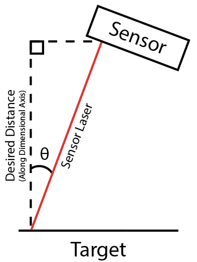
The distance the sensor measures is the hypotenuse. The distance from the target to the sensor along the dimensional axis (the distance you’re looking for) is the adjacent leg of the triangle, and θ is the angle between them. That gives you the following equations:


In the end, the cosine of the angle between the laser light and the dimensional axis is your correction factor. That’s why it’s called a “cosine error.”
The reason trying to measure the error directly like this is so hard is the right angle of the triangle. That point just sits in 3D space, and without very careful measurements (that will likely need multiple references to be possible at all) you will likely cause more error with the fix than the problem caused in the first place.
How much does it matter?
Now that we know that the correction factor is the cosine of the angle between the laser and the dimensional axis, we can tell how much error any difference will give you.
If you are off by 1°, the factor is 0.99985. Put another way, the distance you want is 0.015% less than the distance you measure. Doubling the angle will more than double the error. Halving the angle will less than half the error. Here is a small sample:
| Angle (°) | Correction Factor | Percentage Difference |
| 0.25 | 0.99999 | 0.001% |
| 0.5 | 0.99996 | 0.004% |
| 1 | 0.99985 | 0.015% |
| 2 | 0.99939 | 0.061% |
| 5 | 0.9962 | 0.38% |
| 15 | 0.9659 | 3.52% |
As you can see, the error increases much more quickly the larger the angle gets. The error caused by an angle of 1° or less is less than the error of our most accurate triangulation sensor, the AR700. But as the deviation increases, correcting for the error becomes more and more important.
For our long range sensors, like the AS2100, even the smaller angles can matter at longer distances. At 100 meters, the cosine error of a 0.5° angle is 4 mm, and that’s 4 times the sensor’s accuracy. It is important to evaluate the accuracy needs of every application.
What This Means for Your Application
Acuity Laser sensors are very accurate, but like a sharp knife, they are only accurate when you use them well. If you use them poorly, you won’t get the results you want. You will keep your fingers though. So that’s a positive!
It can be difficult to line up a sensor perfectly in the correct direction. Sometimes, you may have to mount your sensor off axis to get around obstacles. Either way, by knowing how this introduces error, you can correct for it, and keep the knife’s edge precisely where it needs to be.