Triangulation Measurement Principle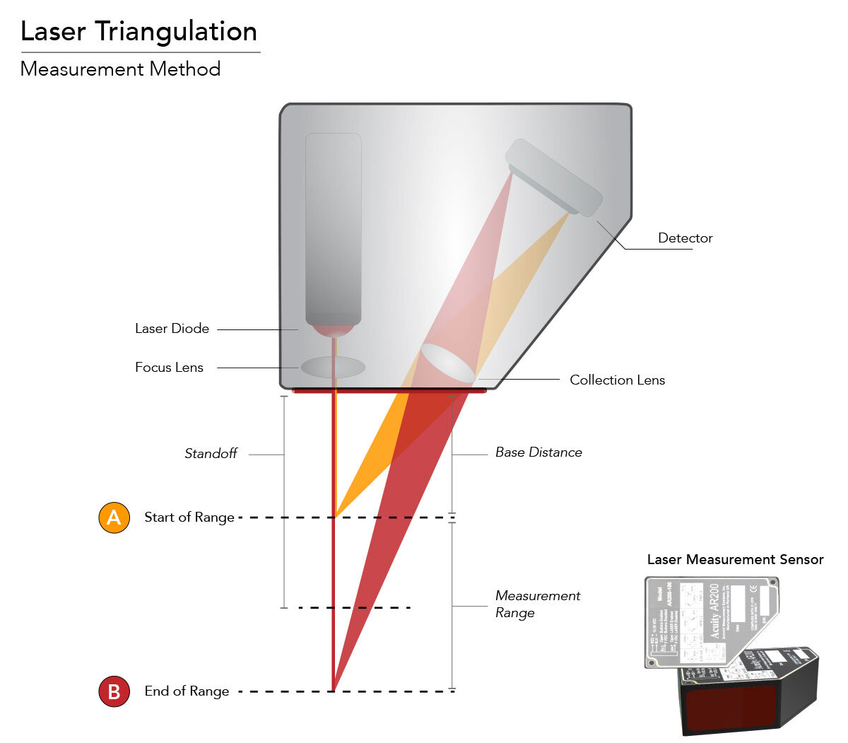
One method for accurately measuring the distance to targets is through the use of laser triangulation sensors. The method is called triangulation because the sensor enclosure, the emitted laser and the reflected laser form a triangle.
The laser beam is projected from the instrument and is diffusely reflected from a target surface to a collection lens. This lens is located a set distance adjacent to the laser emitter. The lens focuses an image of the spot on a linear array detector (CMOS array). The detector views the measurement range from an angle that varies depending on the particular model. The position of the spot image on the pixels of the detector is then processed, either through digital or analog signals, to determine the distance to the target. The detector integrates the light falling on it, so longer exposure times allow greater sensitivity to weak reflections. The beam is viewed from one side so that the apparent location of the spot changes with the distance to the target.
For visual representation, please refer to the simplified Acuity laser triangulation diagram. The laser triangulation principle is seen in both single point triangulation sensors (short range sensors) and in 2D/3D Laser Scanners. In this article, our laser triangulation measurement guide will provide you with high level information regarding laser triangulation characteristics, influences/factors to consider for best laser sensor performance, and best application fields for single point laser triangulation sensors.
Characteristics of laser triangulation sensors
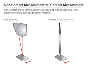 Non-Contact Measurement
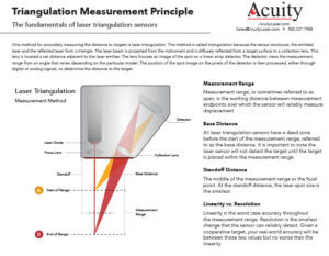
Because laser triangulation sensors are using the location of a light spot from the emitted laser beam to make measurements, this technology allows measurements without making contact with the material; hence the term “non-contact measurement”. Non-contact measurement enables the ability to measure at high speeds and long distances without the drawbacks of damaging the target material or interfering with the target’s path. The ability to measure at long distances and high speeds enables laser displacement sensors to be versatile for endless amounts of applications, including vibration measurements, measuring sensitive materials and inline, high speed process applications.
Measurement Range
Measurement range, or sometimes referred to as span, is the working distance between measurement endpoints over which the sensor will reliably measure displacement. Laser triangulation sensors have different models and are built to measure various measurement ranges. The shorter the sensor measurement range (within the same sensor family), typically the more accurate the laser. This is because there are more detector pixels per unit distance with shorter measurement ranges versus longer ranges. Distance measurement sensors tend to focus on longer ranges, while laser displacement sensors tend to focus on precise short range measurements.
Within a specific range model, as the target material approaches the far end of the measurement range, the accuracy tends to slightly drop off, while still remaining within specifications. Usually, laser calibration certificates are available from manufacturers upon request.
Standoff/Base Distance
All laser triangulation sensors have a dead zone before the start of the measurement range, referred to as the “base distance”. It is important to note the detector inside the laser sensor will not see the target until the target is placed within the measurement range. Since each triangulation sensor is built to precisely measure a certain range, the detector, lens, and laser beam are positioned to only account for the laser spots aligned within the predetermined measurement range. The standoff distance is the term used to describe the middle of the measurement range or the focal point. At the standoff distance, the laser spot size is the smallest (refer to triangulation diagram for visual reference).
Linearity vs. Resolution
A common mix up. In short, linearity is the worst case accuracy throughout the measurement range. Resolution is the smallest change that the sensor can reliably detect. Given a cooperative target, your real-world accuracy will be between those two values but no worse than the linearity. If a small portion of the measurement range is used, the relative error will most likely be closer to the resolution. If the full scale range of the sensor model is used, the error will most likely be closer to the linearity of the sensor.
In general, linearity specifications listed on datasheets are to be reviewed cautiously. Data manipulation or data massaging is very common and it is important to read the footnotes at the bottom of the datasheet. At Acuity, our calibration procedure isn’t done with “proprietary targets,” it is done with a 85% diffused white, matte target at 500Hz. If your application isn’t similar to our calibration conditions, the results may slightly vary. We encourage customers to test demonstration units to let the laser prove itself in your environment and on your material.
Influences/Conditions That Might Impact Laser Sensor Readings
Triangulation sensors are precise measuring devices. All fixturing equipment, environmental conditions, sensor alignment, material color, finish, and orientation must be taken into account. This section is important to note to help ensure optimal performance of other factors.
Proper Sensor Alignment/Fixturing
In general, laser sensors have through-holes that are used to mount and secure the laser sensors. Fixtures should be made to match the location of these holes and maintain the laser head perpendicular to the target of interest. The following will produce the best results for your application.
Mounting: In general, for optimal results, laser sensors should be mounted so the laser beam is as close to a perfect 90° angle to the surface as possible. If the laser sensors are not mounted as close to a perfect 90° angle or if the measurable target is not perpendicular to the laser beam, the reading may be off spec due to a cosine error. Precise fixturing and/or use of a 2-point calibration can help to reduce the cosine error.
Temperature: It is important that the fixture holding a laser triangulation sensor is suitable for the temperature in your environment. Temperature changes can cause expansion and contraction of mounting materials, which results in a distance change to the target. Fixturing material is important to minimize this effect. For example, a steel mounting block is typically recommended over an aluminum block in high heat environments because aluminum structures expand more in the heat, increasing the chances for false distance readings.
Vibration: It is important to ensure that you take precautions during fixturing to minimize vibration. Any vibration will impact the accuracy of the laser and potentially reduce the lifespan of the laser. This is especially important if the sensor is being used for micron to sub-micron resolutions. Any vibration affecting the sensor affects the measurement signal.
Reference Surface: It is important to note that the surface that the target rests on must be taken into account to ensure proper readings. If the surface tolerances are too great, it may impact the sensor’s readings. For example, if trying to precisely measure the height of a target with one laser sensor and the reference material has variations in warpage or surface imperfections, the laser measurements will reflect these imperfections. This will result in an incorrect height measurement of the target material.
Reference surfaces such as an optical breadboard are used to ensure stable surfaces. Motorized reference surfaces such as linear translation stages are used for precise measurements across the material’s profile.
Environmental Conditions
Triangulation sensors are precise measuring devices so environmental factors must be taken into consideration. For best sensor performance, a sensor warm-up time of at least 25 minutes is required to best stabilize the measurement.
Temperature: The most common environmental problem that can affect the accuracy of a laser sensor is temperature. Not only do the electronics exhibit temperature drift, but as discussed before, expansion and contraction of mechanical components and fixturing can physically change the sensor gap. This is especially true when measuring in the micron resolution level.
It is important to note that laser sensors can only operate within a specific temperature range. In order to increase the lifespan & longevity of the laser, if possible avoid placing sensors in environments at the far ends of the temperature limits. Cooling enclosures or heaters can be used to maintain an adequate ambient temperature.
Other environmental conditions: With laser triangulation sensors, it is important to keep the optical path clean and free from obstructions or foreign materials. Dirt, dust and smoke can affect the measurement results.There are two ways environmental factors such as dirt, dust and smoke can be a problem: either the laser can’t see the target through the dust/smoke or the laser can’t see the target because the window is dirty. If the laser can’t see through the dust/smoke, it won’t be able to make the measurement. If the laser can see through the dust/smoke, then you just have to clean the window regularly.
To clean the lens, 98% Isopropyl Alcohol is recommended. For best results, the lens should be wiped with a lint-free, cotton cloth or optical wipe, damp with alcohol, wiped in one direction, and allowed to evaporate. Typically, for ease of troubleshooting, if laser sensors are unable to make a reading due to visibility, an usual output such as an “out of range” error will appear to notify the maintenance team.
Orientating Laser Sensors
For some applications, it is important to understand how to orient the laser sensors for best results.
|
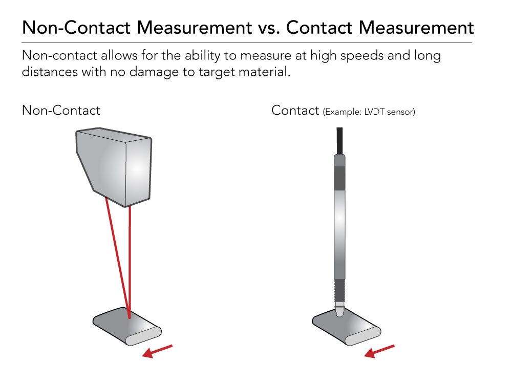
For measurement across an uneven profile or in a tight narrow space:
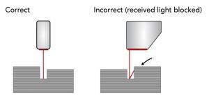
For applications with measurements in a tight or narrow space, it is important to not block the laser beam or the view of the laser detector. The same concept can be applied for the case of bore holes, blind holes, and edges in the surface of moving targets. When profiling across an object that has an uneven surface, an occlusion between the transmitted light and the receiving light may occur causing a blocked signal. Mounting the sensor as shown below will help to reduce the influence of blocked signals when measuring across objects. |
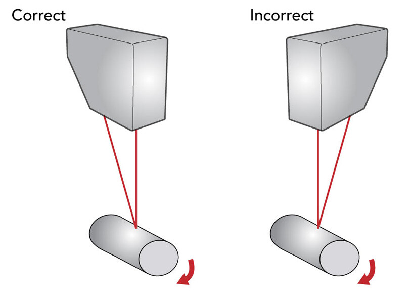
For measurement of rolling objects or curved objects:
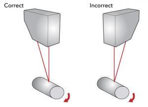
Laser sensors can also be used to measure curved rolling targets. For best results, mount the sensor as shown in the accompanying graphic. The beam should be positioned facing directly toward the center of the curvature. This will basically eliminate any tilt seen by the laser. In addition, ensuring the body of the laser is parallel to the length of the curved object is recommended so that there isn’t an errant specular reflection or an obstruction of the spot from the curve of the object. |
Material Types
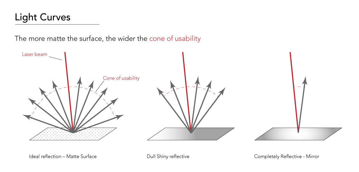
When deciding whether a triangulation sensor will make the measurement needed, the material is a critical aspect. This is true for both the color and finish of the material. These factors must be taken into consideration in every application as the target can impact the overall performance of the sensor. In general terms, triangulation lasers need to be able to see a diffuse reflection of the laser spot from the target to make their measurements. This section is intended to simply serve as a general guideline for different material types, as measurement results on targets vary on a case by case basis.
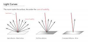 Best material: The most ideal target is a consistent white, matte target. Matte targets are ideal because the laser spot diffuses and scatters on this material over a wider arc then most materials. This is important because the more evenly the light is dispersed or scattered from the target material, the more light will reach the detector, resulting in a more stable signal. White targets are ideal because it allows the most diffused light to reflect back to the detector. More diffused light reaching the detector means that the reading is less affected by external noise and light, typically leading to a better resolution. Examples of these targets are a white piece of matte paper or white ceramic gauge block.
Nearly non-measurable targets: Measuring transparent materials with triangulation lasers is not recommended as the laser light will most likely penetrate through the top surface of the target. If your application demands vibration measurement, and the target is semi transparent, laser sensors have demonstrated success in reading the displacement. However, in general, reliance on precise distance measurement on transparent materials is difficult for laser triangulation sensors. Confocal sensors that use white light technology are more suited to measure transparent materials.
Shiny targets: Shiny targets are not the most ideal targets for laser triangulation sensors because there is less diffused light for the detector to look at. As an extreme example, if you were to shine a laser light at a high grade optical mirror, the laser beam would reflect right back to where it came from. In this case, the detector would never be able to see a diffused laser spot and therefore not be able to make the measurement. However, despite this extreme example, laser triangulation sensors have the ability to measure shiny targets very well. Oftentimes, there is enough diffused reflection off shiny targets for the sensor to perform a reliable reading. For very shiny targets that may be more difficult, inducing a small angle between the laser and the target to make sure that it gets enough light back to the receiver may help achieve the measurement.
Glowing (hot) materials: Glowing hot surfaces can be tough to measure with red laser diode sensors. Red lasers are designed to have a filter to ensure only the red laser wavelength gets to the detector, but when a glowing object emits a lot of light at the same wavelength, the red laser spot can get lost amidst the rest of the light. To counteract this effect, laser manufacturers offer different laser diode wavelengths, such as blue, to ensure measurement on hot, glowing red/orange materials.
Dark materials: Dark surfaces, such as black rubber, can reduce the amount of light the sensor can see, but can be measured with laser triangulation sensors. Adjustments to the exposure time may be required to help adapt to the most efficient light intensity. If the dark surface is absorbing too much light and affecting measurement, more powerful laser diodes can be supplied for optimal performance.
General Principle: As long as the sensor can see the spot on the target, the material should not be an issue. A good rule of thumb is if you can see the light spot on a target material from a naked eye at an angle, then you know your laser detector will also be able to see it.
It is nearly impossible to list specifications for every possible material. Every laser manufacturer experiences the same issues, especially when it comes to the impacts from target materials. This is why, in most situations, we encourage customers to test the unit at their facility before purchasing. At Acuity, we have a comprehensive pool of demonstration units just for testing purposes.
Material Tilt
Tilt angles of materials must be considered when measuring targets, especially when scanning profile surfaces. As referred to above, material target and finish can also impact the performance when it comes to material tilt in relation to the orientation of the laser beam. Slight material tilts, both in the X and Y axis, mostly only impact the readings with highly reflective targets. Since the diffused reflection from target materials varies with different materials, the performance of the tilt angle is liable to the reflectivity of the measuring object surface and is very target dependent.
Real-World Applications
Triangulation sensors are ideally suited for measuring distances, position, and displacement of targets at long ranges with high accuracy. Due to their versatility, laser triangulation sensors are used in numerous applications and industries for non-contact displacement measurement. From automated process control, R&D test and measurement, to OEM integration, many industries benefit from laser sensors. Below is a specific example of a common triangulation application:
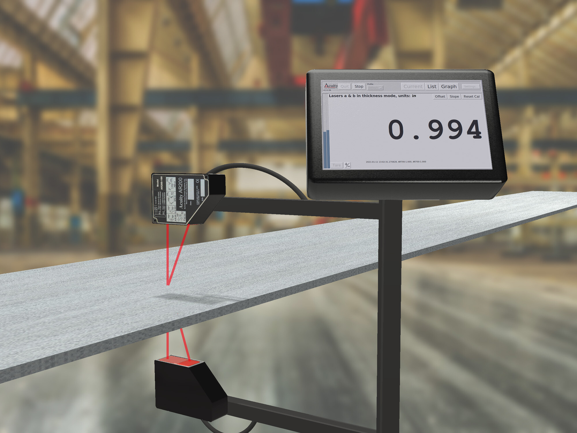
 Acuity Application highlight – Thickness Measurement
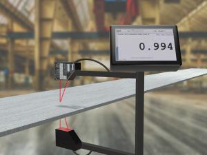
Acuity’s most popular application for laser triangulation sensors is thickness measurement. From inline process measurement to R&D testing, many Acuity customers require precise thickness measurement for quality control and inventory management purposes. Many times Acuity has sold our laser triangulation sensors as a thickness measurement to customers as a replacement for manual contact gauges, LVDT sensors, or customers looking to improve their lower performance laser triangulation sensors.
Laser triangulation thickness measurement can be done with one or two sensors. With one laser, thickness measurement can be done when an object is at rest and in contact with a reference surface. Surface imperfections errors, target warping, material vibration, and other external factors can negatively impact thickness results with one laser. This is why one laser thickness measurement is mostly seen in R&D facilities or carefully controlled environments where all other external factors can be accounted for.
Since many customers do not have the ability to measure the target material under ideal conditions, the most common way to measure thickness is with dual opposing lasers.
When making dual thickness measurements with laser sensors, it is important to align the sensors’ beams as well as take and process measurements from both heads at the exact same time. If these two factors are not considered, a proper thickness measurement will not occur. If properly fixtured, aligned, and synced, factors such as vibration measurement will not impact the thickness reading.
Acuity laser triangulation sensors have performed precisely across many materials such as sheets, foils, insulation, layers, boards, rubber, plates, aluminum, rolled steel, plywood, etc. in many different shapes and forms.
Past thickness examples:
Do You Have a Challenging Application?
Our sales team has decades of experience in the field finding solutions for our customers’ applications. One of our triangulation displacement sensors is patented and much can be learned by reading the patent (USPTO 6,624,899).