")
")
")
")
")
Industry High Precision
The AR700 laser displacement sensor series includes fourteen models with measurement ranges varying from 0.125 inches (3.2 mm) to 50 inches (1270 mm). The AR700 linearity is among the best in the industry at ± 0.03% of the measurement range. All models in this series have a 0.005% resolution throughout the measurement range and some models can even achieve resolutions down to one sixth of a micron. Acuity takes pride in the fact that our specifications are true in real world situations. We encourage customers to ask for previous AR700 calibration certificates to serve as examples of the sensor’s true precision under ideal conditions.
High Speed Capability
The AR700 sensor offers adjustable sampling rates of up to 9400 Hz to satisfy high speed applications. A special trigger mode can be used with the AR700 for synchronization of multiple sensors, but in that case, the maximum speed is reduced to 4500 Hz.
Input/ Output Options
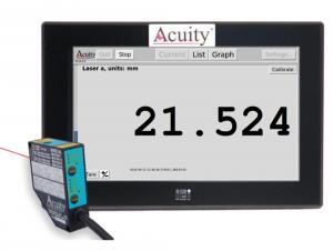
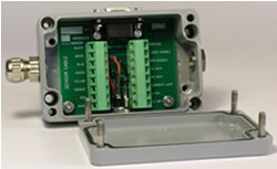
The AR700 laser displacement sensor is standard with a variety of serial and analog outputs. For serial communication, RS232 and RS422 are both included for communication with a computer or PLC. RS232 and RS422 data formats include ASCII English, metric, native and two binary outputs. The sensor can output error codes for: Target too near, Target too far, Target not seen and Laser off.
Analog outputs include a 4-20 mA current loop, 0-10V outputs and two NPN sinking limit switches. All parameters and settings are selectable either from push-buttons on the sensor or through PC serial commands for ease of use.
Built for Applications Needing Top Precision
The AR700 displacement sensor laser offers different sensor options to satisfy a wide variety of environments and applications. Different laser powers and optional bandpass filters can be ordered for improving sensor performance in applications with high ambient light or in measuring distances to targets that are radiating, dark or shiny. All AR700 laser sensors come with programmable options for background light elimination, sample priority, and exposure limit controls to improve the sensor’s performance in certain environments.
All models in this series have a built-in automatic gain control feature to ensure quality measurement despite variations in target colors. The AR700 is commonly used in traditional applications such as thickness, position, and distance measurement, but is most requested in applications that require the upmost accuracy and precision.
AR700 Case Studies
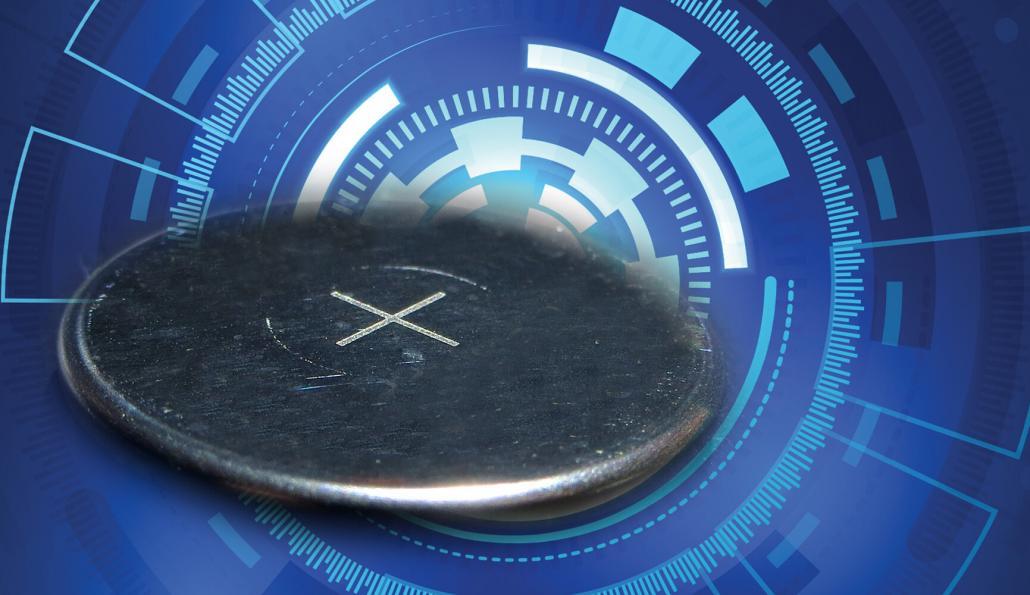
Battery Expansion Laser Displacement Test
A US manufacturer was looking to find a system to precisely measure the displacement of a battery cell during a battery expansion measurement test.
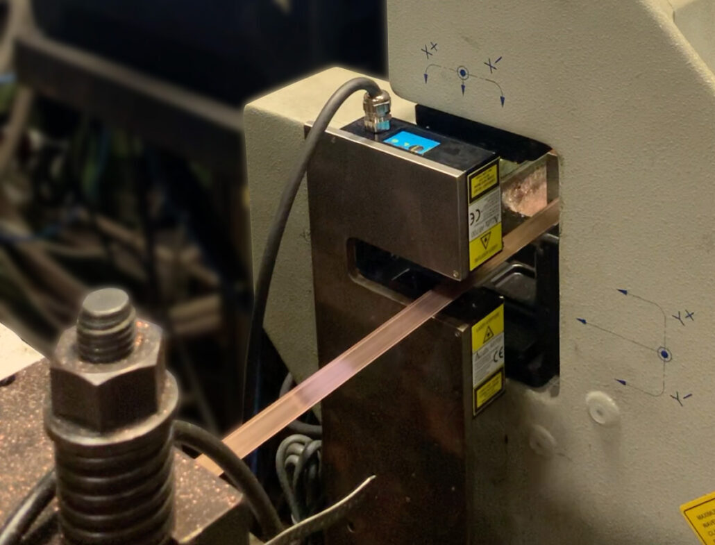
Copper Thickness Measurement for Inline Production
A worldwide manufacturer of copper round stock and copper strips sought — and found — a new solution for their inline copper thickness measurement. The company selected two AR700 – 0125 laser displacement sensors for a dual thickness solution.
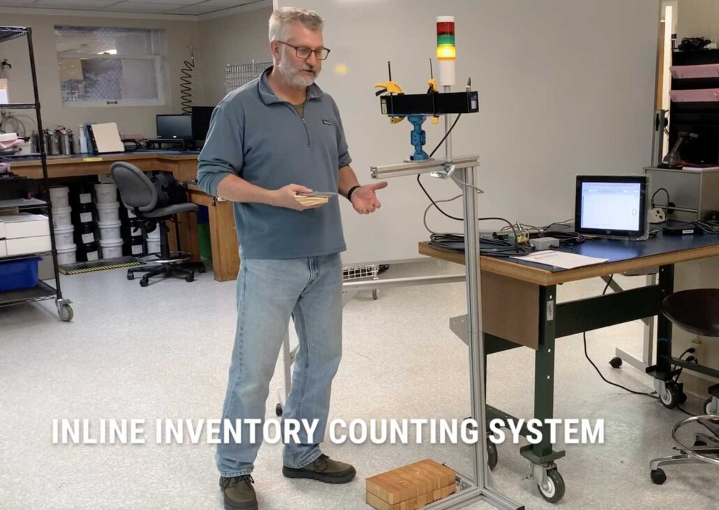
Counting sheet metal stacking for in-line inventory
In this video we showcase how we use our AR700 Laser Displacement Sensor to count & display stacks of sheet metal.

Customization for High Accuracy Triangulation Scenario
An existing Acuity customer asked for a longer range, high accuracy laser triangulation single spot laser sensor to measure deflection. To keep the laser out of an area that can damage the laser sensor, we created the AR700-2 Long range model.
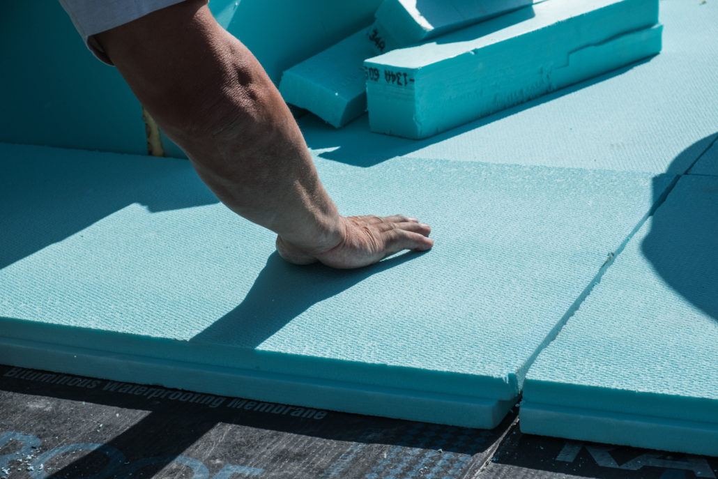
Inline Board Thickness Measurement
Non-contact laser displacement sensors are used to measure the thickness of polystyrene foam-extruded insulation boards in a continuous manufacturing environment.
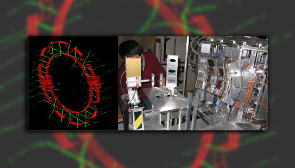
Laser-Based Alignment System
The National Superconducting Cyclotron Laboratory at Michigan State University uses a laser sensor in a system to measure the alignment of detectors. A full presentation of the project can be accessed from their website.
Non-Contact Rubber Measurement with Laser Displacement Sensor
In this example video we show off the abilities of our AR700 laser sensor for non-contact rubber measurement.
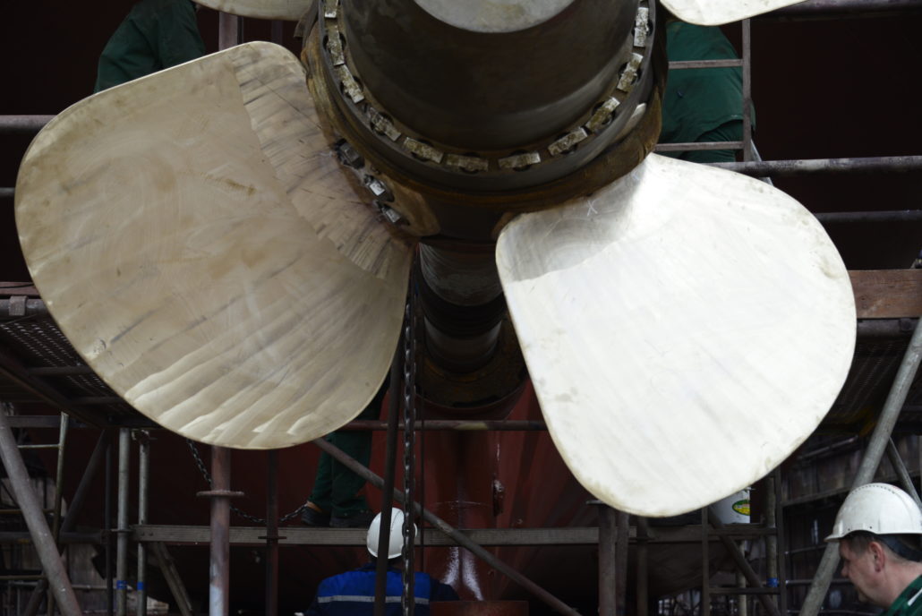
Propeller Blade Profiling
A major North American propeller manufacturer and service company selected a long-range triangulation sensor to measure the profile of its propellers and controllable tip blades during the manufacturing process. Non-contact measuring, like that afforded by laser sensors, is desirable in propeller manufacturing.

Sensors Measure Compression of Bamboo
Investigating the use of bamboo as a primary construction material, a team measured the strain of bamboo samples during materials testing. They required a laser sensor with a long standoff so that it would not get harmed if the bamboo failed and shattered.
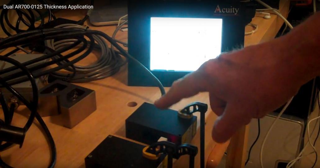
Sub-Micron Thickness Measurement with Dual Laser Sensors
In this application example we zero out two laser displacement sensors for a sub-micron thickness measurement on a 10mm block, with our touch panel displaying between 9.9993mm to 9.9997mm.
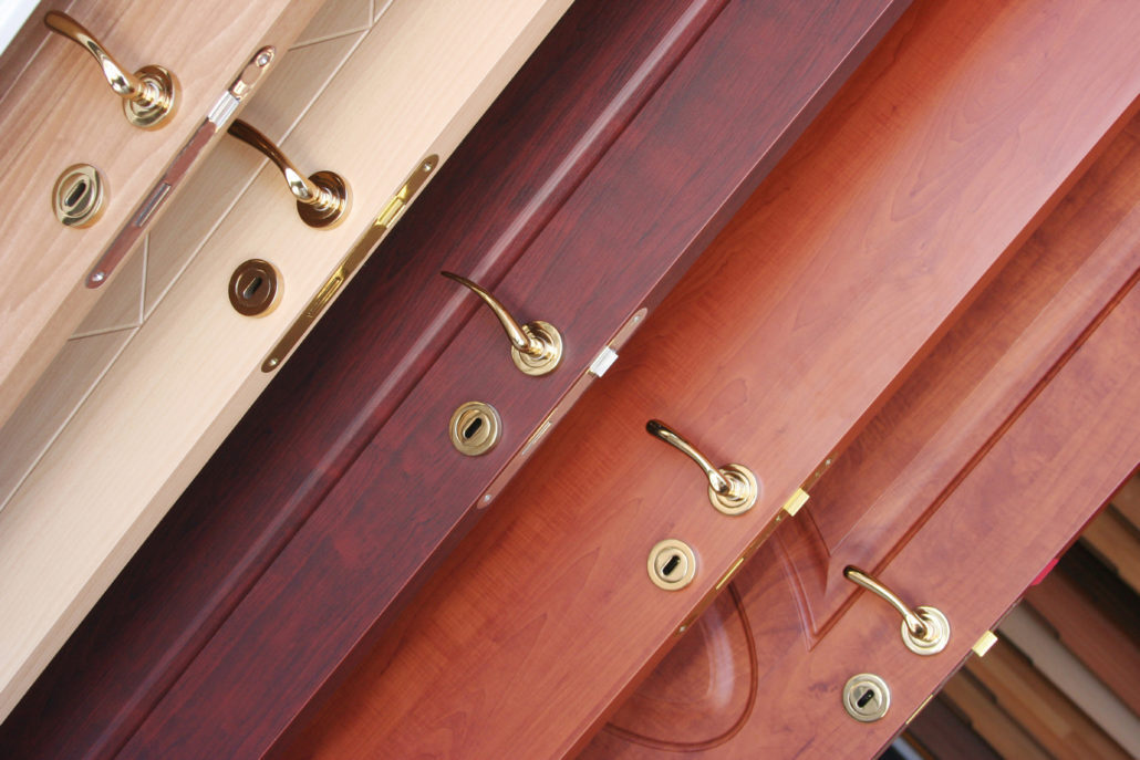
Wooden Door Online Thickness Measurement
One of the issues doors can have is that they are too thick or too thin for a good fit. Laser displacement sensors in a dual opposed mode can make thickness measurements to hold several thousand’s of an inch as doors move down the conveyor line.